Welcome to Our Company -

Programmable Controller PCA1
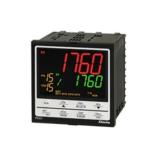
Product Details:
- Accuracy High Precision Control
- Connection Multiple I/O connections, Relay output terminals, panel mounting
- Function Automation Control and Process Logic
- Size Compact (As per manufacturer standard for PCA1)
X
Programmable Controller PCA1 Product Specifications
- Multiple I/O connections, Relay output terminals, panel mounting
- High Precision Control
- Compact (As per manufacturer standard for PCA1)
- Automation Control and Process Logic
- Digital and Analog Inputs
- Relay Output
- Digital LED Display
- ABS Plastic Housing
- DIN Rail/Panel Mount
- Programmable and Manual Modes
- 230V AC
- 0C to 50C
- 500g (approx.)
Product Description
| Output | ||
|---|---|---|
| Control output | Relay contact 1a1b | Control capacity: 3 A 250 V AC (resistive load) 1 A 250 V AC (Inductive load cos=0.4) Electrical life: 100,000 cycles |
| Non-contact voltage (For SSR drive) | 12 V DC15% Max 40 mA (Short circuit protected) | |
| Direct current | 4 to 20 mA DC Resolution: 12000 Load resistance: Max 600 | |
| Event output EV1 EV4 | Relay contact 1a | Control capacity: 3 A 250 V AC (resistive load) 1 A 250 V AC (inductive load cos=0.4) Electrical life: 100,000 cycles Event output EV3, EV4 share one common terminal. |
| Performance | ||
|---|---|---|
| Reference accuracy | Thermocouple | Within 0.2% of each input span1 digit However, R, S input 0 to 200 (32 to 392): Within 6 (12) B input, 0 to 300 (0 to 572): Accuracy is not guaranteed. K, J, E, T, N input, Less than 0 (32): Within 0.4% of input span1 digit |
| RTD | Within 0.1% of each input span1 digit | |
| Direct current,DC voltage | Within 0.2% of each input span1 digit | |
| Cold junction compensation accuracy | Within 1, at 0 to 50 | |
| Input sampling period | 125 ms | |
| Time indication accuracy | 0.1% of setting time | |
| Setting accuracy | Based on Reference accuracy and Cold junction compensation accuracy | |
| Time setting accuracy | 0.1% of setting time | |
| Setting resolution | Temperature | Thermocouple, RTD input without decimal point: 1C (F) Thermocouple, RTD input with decimal point: 0.1C (F) DC voltage, current input: 1 |
| Time | 1 minute or 1 second | |
(0 to 100)C (F)
Thermocouple, RTD input with decimal point:
(0.0 to 100.0)C (F)
DC voltage, current input:
(0 to 1000) (The placement of the decimal point follows the selection.)
(The Wait action is disabled when set to 0 or 0.0.)
| Program Performance | ||
|---|---|---|
| Number of patterns | 16 (Linkable) | |
| Number of steps | 256 (16 steps/pattern) | |
| Repetitions | 0 to 9999 times (Repetitions disabled when set to 0.) | |
| Program time range | 0 to 99 hours 59 minutes/step, or 0 to 99 minutes 59 seconds/step (When is set, Fixed value control is performed using step SV.) | |
| Wait value | ||
| Specifications | ||
|---|---|---|
| Input | Thermocouple | K, J, R, S, B, E, T, N, PL-II, C(W/Re5-26) External resistance: 100 max. However, B input: External resistance: 40 max. |
| RTD | Pt100, JPt100 3-wire type Allowable input lead wire resistance: 10 max. per wire However, Pt100, -100.0 to 100.0 : 5 max. per wire | |
| Direct current | 0 20 mA DC, 4 20 mA DC Input impedance: 50 Allowable input current: 100 mA max. | |
| DC voltage | 0 10 mV DC, -10 10 mV DC, 0 50 mV DC, 0 100 mV DC, 0 1 V DC: Input impedance: 1 M min. Allowable input voltage: 5 V DC max. Allowable signal source resistance: 2 k max. (0 1 V DC) 200 max. (0 100 mV DC, 0 50 mV DC) 40 max. (-10 10 mV DC) 20 max. (0 10 mV DC) 0 5 V DC, 1 5 V DC, 0 10 V DC Input impedance: 100 k min. Allowable input voltage: 15 V DC max. Allowable signal source resistance: 100 max. | |
Smart Automation with Reliable Precision
Harness the efficiency of the PCA1 for process automation. With its advanced programmable and manual modes, combined with high accuracy, the controller streamlines operations across varied applications. The digital LED display ensures real-time, readable status updates for seamless management.
Versatile Configuration for Diverse Environments
Engineered with multiple I/O connections and adaptable mounting options, the PCA1 integrates effortlessly into industrial panels or DIN rails. Its robust ABS plastic body is built to withstand demanding environments, ensuring longevity while minimizing maintenance requirements. Exported and supplied across India, it's trusted by distributors and service providers alike.
FAQ's of Programmable Controller PCA1:
Q: How do I mount the PCA1 controller in my automation panel?
A: You can easily install the PCA1 using either DIN rail or panel mounting methods, making it suitable for various automation cabinets and process control panels. The compact size ensures it fits manufacturer-standard enclosures.Q: What types of inputs and outputs does the PCA1 support?
A: The controller accepts both digital and analog input signals and provides relay output terminals for flexible connections to your automation system, enabling broad compatibility with a range of devices.Q: When should I use programmable vs. manual operation modes on the controller?
A: Use manual mode for simple, direct control tasks and switch to programmable mode when you need complex logic, scheduling, or process automation, depending on your application's requirements.Q: Where can the PCA1 controller be applied?
A: The PCA1 is suitable for industrial, commercial, and process automation settings, and can be efficiently integrated into projects needing high-precision control and process logic across India.Q: What benefits does the digital LED display provide?
A: The digital LED display offers clear, instant readouts of system status and parameters, improving monitoring accuracy and making it easier to troubleshoot or adjust settings during operation.Q: How does the PCA1 handle high-precision automation tasks?
A: With advanced processing and reliable relay outputs, the controller delivers precise logic control suitable for sensitive automation processes, reducing errors and increasing overall system efficiency.Tell us about your requirement

Price:
Quantity
Select Unit
- 50
- 100
- 200
- 250
- 500
- 1000+
Additional detail
Mobile number
Email

Other Products in 'Profile Controllers' category


Contact Details
- Shop No: 303-304, Block - C, 3rd Floor, Pushp Business Campus, S P Ring Road, Vastral, Ahmedabad - 382418, Gujarat, India
- Phone : 08045478447
GST : 24AAJCP7915M1ZX
- Mr Ramnarayan Ajmera (Manager-Business Development)
- Mobile : 08045478447
- Send Inquiry
Our Products
- Temperature
- Pressure
- Level
- Flow
- Liquid & Gas Analysis
- Portable Temperature Datalogger
- Humidity
- Monitor Indicator
- Control
- Air Flow And Velocity Transmitter
- Vibration Sensors
- Differential Pressure Transmitter
- Automation
- Wireless Sensors & Transmitters
- Digital Manometer
- ATEX - Flameproof Product
- Low Pressure Generator & Calibrators
- Pressure Gauge
- Chart Recorder
- Temperature & Humidity Transmitter
- Carbon Dioxide Transmitter
- VOC Transmitter
- Infrared Temperature Sensors And Pyrometers
- Pressure Transmitter
- RTD Temperature Probes
- Temperature Transmitters
- Differential Presure Switch
- Indicator Controller Transmitters
- Level Transmitter Solid & Liquid
- Milk Silo Level Transmitters
- Point Level Switch - Solid & Liquid
- Pressure Switch
- Flow measuring Devices (Pitot Tube)
- Ozone Analyzer
- Inline Optical Brix Transmitter
- PH-ORP Electrode
- pH Probe housings & accessories
- Probe Housing
- Turbidity Sensor
- Infrared Temperature Sensors
- Temperature And Humidity Transmitter
- Process PID Controller
- Profile Controllers
- Control Unit Of Pneumatic Retractable Ph Housings
- Isolted Signal Transmitter
- Positioning System - Automatic Format Changeover
- Smart Positiong Drive
- Thyristor Power Controller
- Digital Temperature Switch
- Handheld Digital Probe Thermometer
- Differential Pressure Gauge
- Digital Differential Pressure Gauge
- Gas Pressure Switch
- Vacuum Pressure Switches
- Boot Level Switch
- Hydrostatic Level Transmitter
- Pendulum Level Switch
- Clean Room Differential Pressure Indicator
- Differential Pressure & Flow Controller
- Pressure Gauges
- Digital Electronic Pressure Switch
- Draft Pressure Transmitter
- Chute Jam Level Switch
- Overflow Switch for Screw-Chain Conveyor
- Point Level Switch
- Air Flow Switch
- Averaging Flow Sensor
- Plug-in Type
- Terminal Block Type
- Flow Indicators & Totalizer
- Portable Air Velocity meter
- Stack Air Velocity Transmitter
- Broken Bag Leak Detector
- Carbon Dioxide Transmitters
- Conductivity Transmitters
- Dissolved Oxygen Analyzer
- Duct smoke detector
- Filter monitoring
- Inline Process Refractometer
- Inline Total Solid (TS) Transmitter
- Optical Density Transmitter (Biomass)
- Immersion fittings
- Retractable housings - manual
- Retractable housings - pneumatic
- Static probe housings
- pH Transmitter & Controller
- Solid Flow Monitor
- Stack Dust Monitor (QAL 1 Certified)
- Indoor Air Quality Transmitter
- Particulate Matter Transmitter
- Digital Process Indicator
- Loadcell Indicator
- Hiperdrive Positioning Systems
- Positioning Systems 3 Series
- Other Positioning Systems
- ATEX Boot Level Switch
- ATEX Broken Bag Leak Detector
- ATEX Flameproof Air Differential Pressure Switch
- ATEX IR Temperature Sensors
- ATEX Membrane Level Switch
- ATEX Pendulum Level Switch
- ATEX Pressure Switch 901P EX
- ATEX vibration sensor
- Flameproof Level Switches & Transmitters
- Flameproof Pressure Transmitter
- Building Controllers
- Pressure Switches
- Digital Portable Manometer
- ORP Transmitters
- Free Chlorine Analyzer
- Total Chlorine Analyzer
- Chlorine Dioxide Analyzer
- Integrated BLDC Motor
- ATEX Differential Pressure Switch 930 EX
- IAQ Sensors
- CO2 Transmitter
 Send Inquiry
 Send SMS
 Call Me Free
PARSHVI TECHNOLOGY (INDIA) PRIVATE LIMITED
All Rights Reserved.(Terms of Use)
Developed and Managed by Infocom Network Private Limited.
Developed and Managed by Infocom Network Private Limited.
