Welcome to Our Company -

Programmable Controller PCB1
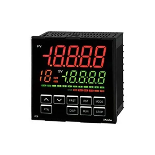
Product Details:
- Accuracy High signal processing accuracy for precise control
- Connection Screw terminal connectors for secure wiring
- Pressure Not applicable (electronic control device)
- Function Programmable logic controller for industrial automation
- Size Standard PCB size (approx. 100mm x 80mm)
X
Programmable Controller PCB1 Product Specifications
- High signal processing accuracy for precise control
- Screw terminal connectors for secure wiring
- Standard PCB size (approx. 100mm x 80mm)
- Programmable logic controller for industrial automation
- Not applicable (electronic control device)
- 6 relay outputs
- Machine automation, process control, and other industrial purposes
- 8 digital inputs
- 24V DC
- Supported via PC software interface
- 0C to 55C
- Relay and transistor outputs available
- Panel Mount
- LED status indicators for each channel
- FR4 glass epoxy PCB
Product Description
| Output | ||
|---|---|---|
| Control output | Relay contact 1a1b | Control capacity: 3 A 250 V AC (resistive load) 1 A 250 V AC (Inductive load cos=0.4) Electrical life: 100,000 cycles Minimum applicable load: 10 mA 5 V DC |
| Non-contact voltage (For SSR drive) | 12 V DC15% Max 40 mA (Short circuit protected) | |
| Direct current | 4 to 20 mA DC Resolution: 12000 Load resistance: Max 600 | |
| Event output EV1 EV4 | Relay contact 1a | Control capacity: 3 A 250 V AC (resistive load) 1 A 250 V AC (inductive load cos=0.4) Electrical life: 100,000 cycles Minimum applicable load: 10 mA 5 V DC |
| Control output OUT2 (Optional) | Relay contact | Control capacity: 3 A 250 V AC (resistive load) 1 A 250 V AC (inductive load cos=0.4) Electrical life: 100,000 cycles Minimum applicable load: 10 mA 5 V DC |
| Non-contact voltage(for SSR drive) | 12 V DC15% Max. 40 mA (Short circuit protected) | |
| Direct current | 4 to 20 mA DC Resolution: 12000 Load resistance: Max. 550 | |
| Transmission output(Optional) | Resolution | 12000 |
| Output | 4 to 20 mA DC (Load resistance: Max. 550 ) | |
| Output accuracy | Within 0.3% of Transmission output span | |
| Response time | 400 ms + Input sampling period (0%>90%) | |
| Insulated power output(Optional) | Output voltage | 243 V DC (When load current is 30 mA DC) |
| Ripple voltage | Within 200 mV DC (When load current is 30 mA DC) | |
| Max. load current | 30 mA DC | |
| Performance | ||
|---|---|---|
| Base accuracy | At ambient temperature 23 (for a single unit mounting) | |
| Thermocouple | Within 0.2% of each input span1 digit However, R, S input 0 to 200 (32 to 392): Within 6 (12) B input, 0 to 300 (0 to 572): Accuracy is not guaranteed. K, J, E, T, N input, Less than 0 (32): Within 0.4% of input span1 digit | |
| RTD | Within 0.1% of each input span1 digit | |
| Direct current, DC voltage | Within 0.2% of each input span1 digit | |
| Effect of ambient temperature | Within 50 ppm/ of each input span | |
| Input sampling period | 125 ms | |
| Time setting accuracy | Within 0.5% of setting time | |
DC voltage, current input: 0 to 20% of scaling span (The placement of the decimal point follows the selection.)
(The Wait function is disabled when set to 0 or 0.0.)
| Program Performance | ||
|---|---|---|
| Number of patterns | 10 (Linkable) | |
| Number of steps | 100 (10-steps/pattern) | |
| Number of repetitions | 0 to 10000 times (Repetitions disabled when set to 0.) | |
| Program time range | 0 to 99 hours 59 minutes/step, or 0 to 99 minutes 59 seconds/step (When is set, Fixed value control is performed using step SV.) | |
| Wait value | ||
| Specifications | ||
|---|---|---|
| Input | Thermocouple | K, J, R, S, B, E, T, N, PL-II, C(W/Re5-26) External resistance: 100 max. However, B input: External resistance: 40 max. |
| RTD | Pt100, JPt100 3-wire type Allowable input lead wire resistance: 10 max. per wire However, Pt100, -100.0 to 100.0 : 5 max. per wire | |
| Direct current | 0 20 mA DC, 4 20 mA DC Input impedance: 50 Allowable input current: 50 mA max. | |
| DC voltage | 0 to 1 V DC Input impedance: 1 M min. Allowable input voltage: 5 V DC max. Allowable signal source resistance: 2 k max. 0 to 5 V, 1 to 5 V, 0 to 10 V DC Input impedance: 100 k min. Allowable input voltage: 15 V DC max. Allowable signal source resistance: 100 max. | |
| Event input (Optional) | Input points | 2 points |
| Circuit current when closed | Approx. 16 mA | |
| Action | Edge action When the power is turned on, level action is engaged. | |
Efficient Control for Industrial Automation
PCB1 delivers reliable performance in automation and process control environments. Its ability to interface with multiple sensors and actuators makes it an ideal solution for manufacturers seeking accurate and dependable logic control. With both relay and transistor outputs available, industrial users gain flexibility in managing diverse systems seamlessly.
User-Friendly Programming and Installation
The controller features convenient panel mounting and screw terminal connectors, simplifying the installation process. Programming is performed through an intuitive PC software interface, allowing users to customize logic functions effortlessly. LED status indicators for each channel provide instant feedback, aiding troubleshooting and monitoring.
FAQ's of Programmable Controller PCB1:
Q: How is the Programmable Controller PCB1 programmed for custom applications?
A: Programming is performed via the provided PC software interface, allowing users to configure logic functions and control schemes to suit specific industrial tasks. The process is simplified through a user-friendly graphical interface.Q: What are the benefits of using both relay and transistor outputs?
A: Having both relay and transistor outputs increases system versatility, permitting control of different load types, such as solenoids, motors, and electronic devices, within a single controller setup.Q: When should PCB1 be mounted on a panel?
A: PCB1 is designed for panel mounting, recommended during initial system setup in industrial environments. Panel mounting ensures secure installation and efficient integration into control cabinets.Q: Where is this controller typically used?
A: It is commonly deployed in machine automation, process control, and various industrial applications that demand accurate programmable logic control and high compatibility with multiple sensors and actuators.Q: What process is followed for wiring connections?
A: Wiring is accomplished through screw terminal connectors, which provide reliable connections and prevent accidental disconnections. Secure wiring is essential for continuous industrial operation and safety.Q: How does the LED status indication support operation?
A: Each channel features an LED status indicator, providing instant visual feedback on input and output statuses. This facilitates real-time monitoring and simplifies troubleshooting during maintenance or commissioning.Tell us about your requirement

Price:
Quantity
Select Unit
- 50
- 100
- 200
- 250
- 500
- 1000+
Additional detail
Mobile number
Email

Other Products in 'Profile Controllers' category


Contact Details
- Shop No: 303-304, Block - C, 3rd Floor, Pushp Business Campus, S P Ring Road, Vastral, Ahmedabad - 382418, Gujarat, India
- Phone : 08045478447
GST : 24AAJCP7915M1ZX
- Mr Ramnarayan Ajmera (Manager-Business Development)
- Mobile : 08045478447
- Send Inquiry
Our Products
- Temperature
- Pressure
- Level
- Flow
- Liquid & Gas Analysis
- Portable Temperature Datalogger
- Humidity
- Monitor Indicator
- Control
- Air Flow And Velocity Transmitter
- Vibration Sensors
- Differential Pressure Transmitter
- Automation
- Wireless Sensors & Transmitters
- Digital Manometer
- ATEX - Flameproof Product
- Low Pressure Generator & Calibrators
- Pressure Gauge
- Chart Recorder
- Temperature & Humidity Transmitter
- Carbon Dioxide Transmitter
- VOC Transmitter
- Infrared Temperature Sensors And Pyrometers
- Pressure Transmitter
- RTD Temperature Probes
- Temperature Transmitters
- Differential Presure Switch
- Indicator Controller Transmitters
- Level Transmitter Solid & Liquid
- Milk Silo Level Transmitters
- Point Level Switch - Solid & Liquid
- Pressure Switch
- Flow measuring Devices (Pitot Tube)
- Ozone Analyzer
- Inline Optical Brix Transmitter
- PH-ORP Electrode
- pH Probe housings & accessories
- Probe Housing
- Turbidity Sensor
- Infrared Temperature Sensors
- Temperature And Humidity Transmitter
- Process PID Controller
- Profile Controllers
- Control Unit Of Pneumatic Retractable Ph Housings
- Isolted Signal Transmitter
- Positioning System - Automatic Format Changeover
- Smart Positiong Drive
- Thyristor Power Controller
- Digital Temperature Switch
- Handheld Digital Probe Thermometer
- Differential Pressure Gauge
- Digital Differential Pressure Gauge
- Gas Pressure Switch
- Vacuum Pressure Switches
- Boot Level Switch
- Hydrostatic Level Transmitter
- Pendulum Level Switch
- Clean Room Differential Pressure Indicator
- Differential Pressure & Flow Controller
- Pressure Gauges
- Digital Electronic Pressure Switch
- Draft Pressure Transmitter
- Chute Jam Level Switch
- Overflow Switch for Screw-Chain Conveyor
- Point Level Switch
- Air Flow Switch
- Averaging Flow Sensor
- Plug-in Type
- Terminal Block Type
- Flow Indicators & Totalizer
- Portable Air Velocity meter
- Stack Air Velocity Transmitter
- Broken Bag Leak Detector
- Carbon Dioxide Transmitters
- Conductivity Transmitters
- Dissolved Oxygen Analyzer
- Duct smoke detector
- Filter monitoring
- Inline Process Refractometer
- Inline Total Solid (TS) Transmitter
- Optical Density Transmitter (Biomass)
- Immersion fittings
- Retractable housings - manual
- Retractable housings - pneumatic
- Static probe housings
- pH Transmitter & Controller
- Solid Flow Monitor
- Stack Dust Monitor (QAL 1 Certified)
- Indoor Air Quality Transmitter
- Particulate Matter Transmitter
- Digital Process Indicator
- Loadcell Indicator
- Hiperdrive Positioning Systems
- Positioning Systems 3 Series
- Other Positioning Systems
- ATEX Boot Level Switch
- ATEX Broken Bag Leak Detector
- ATEX Flameproof Air Differential Pressure Switch
- ATEX IR Temperature Sensors
- ATEX Membrane Level Switch
- ATEX Pendulum Level Switch
- ATEX Pressure Switch 901P EX
- ATEX vibration sensor
- Flameproof Level Switches & Transmitters
- Flameproof Pressure Transmitter
- Building Controllers
- Pressure Switches
- Digital Portable Manometer
- ORP Transmitters
- Free Chlorine Analyzer
- Total Chlorine Analyzer
- Chlorine Dioxide Analyzer
- Integrated BLDC Motor
- ATEX Differential Pressure Switch 930 EX
- IAQ Sensors
- CO2 Transmitter
 Send Inquiry
 Send SMS
 Call Me Free
PARSHVI TECHNOLOGY (INDIA) PRIVATE LIMITED
All Rights Reserved.(Terms of Use)
Developed and Managed by Infocom Network Private Limited.
Developed and Managed by Infocom Network Private Limited.
